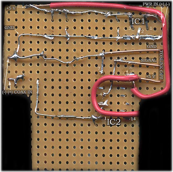
- The power regulation circuit starts at the top right and proceeds leftward.
- I arranged the components to allow the ground line to run continuously until it reaches the wires to the TOSlink transmitter.
- The longer red wire takes the +5V output of the regulator circuit to IC2 and an output wire to run to the TOSlink unit. The second, U-shaped red cable under IC2 is a silly mistake on my part...I ran the original cable to the wrong pin on IC2, and used the short U to jump it over to pin 14.
- The only thing covered up by the U wire is the direct connection between pins 2 and 3 of IC2 - I used a small piece of lead wire (you should have plenty from cutting the leads of other components).
- Your board will probably look much neater than the above - I cracked my last board when I tried to trim it with wire cutters (bad idea :), so I desoldered everything and transferred to a new board.
|
|