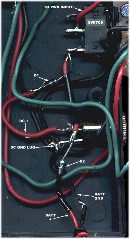
- The battery ground wire is connected to the DC ground lug, and another wire runs from the DC ground lug to the circuit board power input.
- The battery positive wire has a diode soldered inline (D2) - the black material you see on the line is heat shrink tubing. The battery positive wire is connected to the bottom switch terminal - note that the battery positive is not connected to any of the terminals of the DC power jack. It is simply passing over them.
- The DC positive wire also has its own diode soldered inline (D1), and is also connected directly to the bottom switch terminal.
- A wire runs from the other switch terminal to the circuit board power input. The terminals at the top of the switch are just for the switch's LED - if you purchased a regular SPST switch there will only be two terminals.
|
|